FPS vs MS
Frames per second (FPS)
One of the most common benchmarks used in measuring the graphics performance of a video game is the frame rate or frames per second.
FPS is the number of times the image on the screen is refreshed each second.
However using FPS as the performance measurement is wrong most of the time. FPS measurement is not uniform and saying "performance increases by 5fps" when you talk about going up from 10 to 15fps means huge 33.34ms increase, while if you talk about 55 and 60 fps, it gives 1,5ms.
Having 60fps target, you have 16.67ms limit for all your processing.
The actual cost of features is a period of time, not a number of frames.
Milliseconds per frame (ms)
The inverse of the frames per second (FPS) gives us the seconds per frame (SPF); there are 1000 milliseconds in a second.
1000/fps = ms/frame
60fps means 1000/60 = 16.666ms per frame
While the frames per second increase, the number of milliseconds decreases at a slower rate:
- 90fps = 11.11ms - for VR to reduce motion sickness
- 60fps = 16.67ms - action games
- 50fps = 20ms
- 40fps = 25ms
- 30fps = 33.34ms - adventure, etc
- 20fps = 50ms
- 10fps = 100ms
Example: we have a scene running at 35fps - 1000/35 = 28.57ms, let's say we want to use HBAO+ Ultra which takes 4.8ms - 28.57 + 4.8 = 33.37ms, that means our scene is now running at 30fps.
Learn More
How do we influence this
FPS drops are caused by CPU and GPU taking longer time to process the frames.
- For CPU, most demanding are draw calls, positions, math and visibility (physics, AI, skeletal animations, projectiles, etc.)
- GPU is often limited by fillrate or memory bandwidth. Typical problems are shaders, lights, dynamic shadows, translucency, overdraw.
Polycount & LODs
A Level of Detail model (LOD) is a lower-resolution version of a game model. LOD0 is the original mesh, the higher the LOD the fewer vertices to be processed. This leads to big performance improvements by reducing the cost on the CPU and GPU vertex processing.
Dynamic lights calculate each vertex no matter the size on screen, you have to be careful with triangle count covered by dynamic lights, because a 10k mesh is just as expensive up close as it is far away for shadow calculation.
GDC presentation from Simplygon about LODs and how they affect overshading.
General advises:
- Watch the number of vertices and faces of the models, check for the polycount limits. Reduce tris and remove polys of the model which are never visible.
- Make sure that all of the models have LODs (Except the very simple ones like blocks). Look for your models LODs distances, for example you may have the model on such a distance where it's already 100px small on the screen but still is in LOD0 with 10k tris.
- Do not leave hidden objects and vegetation under terrain or inside other objects, and preferably terrain parts under objects. It wastes the CPU and GPU processing time for nothing.
- Make assets modular. Keep the number of different materials per scene low, and share as many materials between different objects as possible.
- Use bilboards on distance to fake detailed geometry.
Overshading
Overshading is caused by tiny or thin triangles and can really hurt performance by wasting a significant portion of the GPU’s time. Overshading is a consequence of how GPUs process pixels in quads, blocks of 2x2 pixels. It’s done like this so the hardware can do things like comparing UVs between pixels to calculate appropriate mipmap levels. [3]
This means that if a triangle only touches a single pixel of a quad, the GPU still processes the whole quad and just throws away the other three pixels, wasting 75% of the work. [3]
Small triangles are bad for performance.
Filling the frame buffer with anything larger than 16 by 16 tiles have no effect on the GPU performance. The primitive minimum size in pixels is pretty much the same for all vendors. Covering less than 8 by 8 pixels, with two triangles starts to have a significant impact on performance and it grows exponentially. [4]
If we want some good performance, let's set the minimum size to about 8 pixels per triangle. It's recommended to have triangles at least 16 pixels in size.
Tiny triangles are also a problem because GPUs can only process and rasterize triangles at a certain rate, which is usually relatively low compared to how many pixels it can process in the same amount of time. With too many small triangles, it can’t produce pixels fast enough to keep the shader units busy, resulting in stalls and idle time – the real enemy of GPU performance. [4]
Culling
Culling explained on Crytek docs.
Culling is completely excluding objects from processing when they are outside the view. This is an effective way to reduce both the CPU and GPU load.
When multiple meshes are merged into a single object, their individual bounding volumes must be combined into a single large volume that is big enough to enclose every mesh. This increases the likelihood that the visibility system will be able to see some part of the volume, and so will consider the entire collection visible. That means that it becomes a draw call, and so the vertex shader must be executed on every vertex in the object - even if very few of those vertices actually appear on the screen. This can lead to a lot of GPU time being wasted because the vertices end up not contributing anything to the final image. [3]
Opacity & Overdraw
Overdraw happens when the same pixel is drawn multiple times (when objects are drawn on top of other).
The thing that impacts the fillrate the most is transparent stuff like particles with alpha blending. Limit the amount of opacity maps you use and their impact on the scene. If your map has a lot of opacity it’s better to add a few extra cuts and reduce the opacity area than to save a few polygons.
There's an article on particle optimizations for the further reading
Translucency is also very heavy for performance, never use translucency unless absolutely necessary.
Lighting & Shadows
Static lights are faster than dynamic lights, cull dynamic lights as early as possible, minimize the number of objects they affect. Spot lights are cheaper than the point lights. One point light costs as much as 6 spot lights. Try to avoid lighting spheres or conuses to overlap each other. Reduce lights amount and cast distance as much as possible.
Bake as much lighting effects as possible.
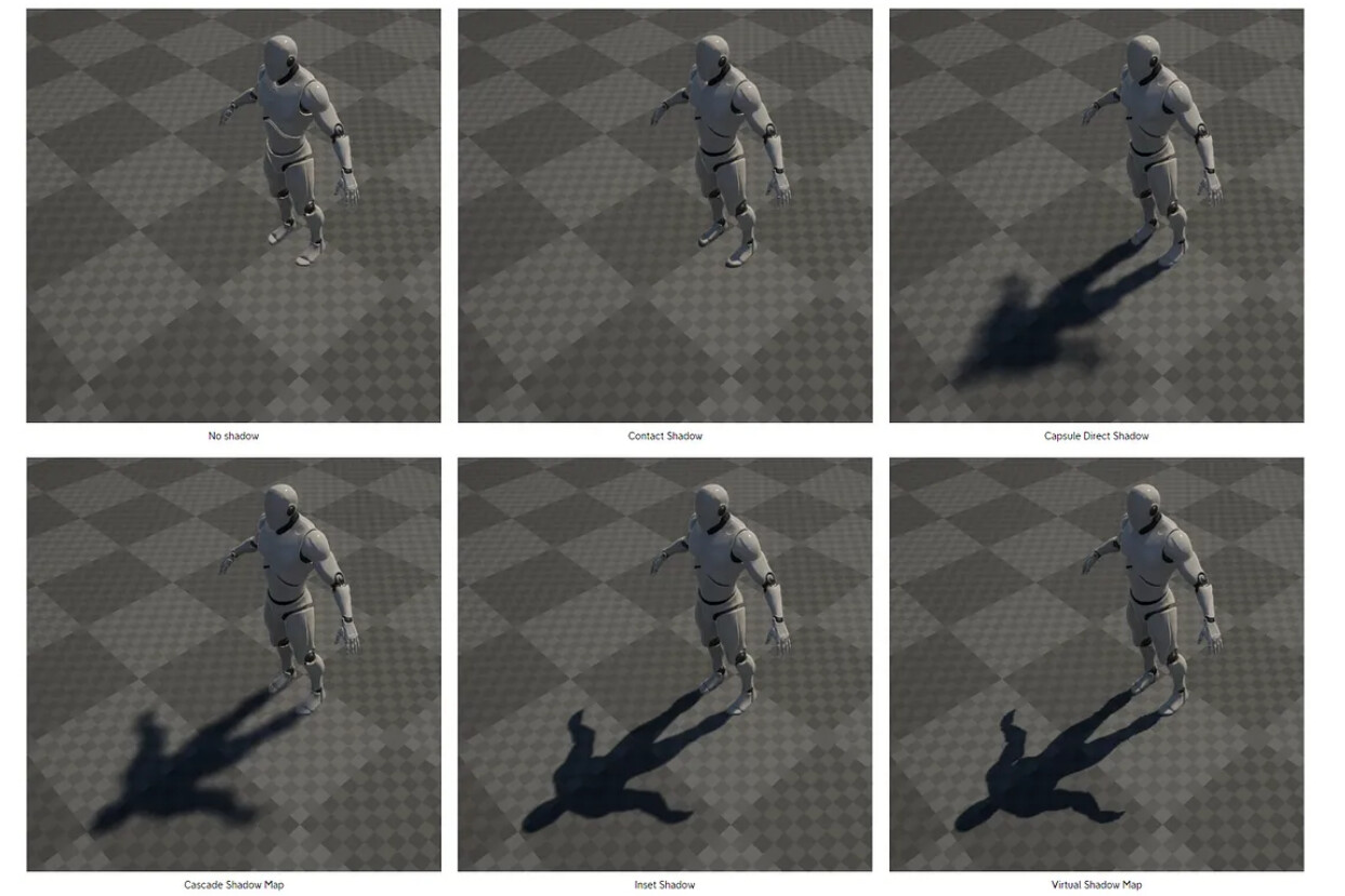
Lights can optionally cast shadows. This gives them greater realism but has a bigger performance cost. Lights and realtime shadows have a big impact on performance, these effects give extra draw calls for the CPU and extra processing on the GPU. Also, shadow maps resolution has a moderate performance cost.
As mentioned earlier, triangle count is rarely a problem. But it matters for shadow casting, adding the processing costs to that.
Disable shadow casting where possible.
Soft shadows have a greater rendering overhead than hard shadows but this only affects the GPU and does not cause much extra CPU work.
Draw Calls
CPU is often limited by the number of batches that need to be rendered. [5]
Dip - DrawIndexedPrimitives. DrawElements in OpenGL
Draw call commands are given by CPU to GPU, to render a mesh. The command only points to a mesh which shall be rendered and doesn’t contain any material information. After the command is given, the GPU takes the render state values (material, textures, shaders etc…) and all the vertex data to convert this information into pixels on your screen. [13]
Every mesh with a different material will require a separate Draw Call. [13]
Reducing Draw Calls will reduce overhead for the GPU and clearing up CPU usage for other processing.
If your frame rate is fine, there is no need to worry about Draw Calls.
If you're not bound on Draw Calls, it's better not to reduce them as that affects culling, making it less precise.
How do we influence this
The main reason to make fewer draw calls is that GPUs can transform and render triangles much faster than you can submit them. If you submit few triangles with each call, the CPU won't be able to feed the GPU fast enough and the GPU will be mostly idle. [15 - actually is also quoted from forum discussion] But also, if the mesh exceeds the vertex limit for a single batch, then it will be split into more than one batch, and cause more draw calls.
Try to keep the number of UV mapping seams and hard edges (doubled-up vertices) as low as possible.
Note that the actual number of vertices that graphics hardware has to process is usually not the same as the number reported by a 3D application. Modeling applications usually display the number of distinct corner points that make up a model (known as the geometric vertex count). For a graphics card, however, some geometric vertices need to be split into two or more logical vertices for rendering purposes. A vertex must be split if it has multiple normals, UV coordinates or vertex colors. [8]
Do not make too many too trivial shapes.
Do not make millions of shapes with only a few vertices. Merge your shapes to have thousands of triangles in a single shape.
BUT:
Do not make too few shapes.
This one is explained above in the culling section.
Each shape is passed as a whole, and shapes may be culled. By using only a few very large shapes, you make this culling worthless. (In most cases you would not want to combine all the telephone poles into a single model, because then the renderer couldn't cull the unseen meshes, so ALL the triangles would have to be loaded.) [2]
Draw calls often have a more significant impact on performance than polycount.
Which means if you need some extra polys to make a model smoother - go for it.
Even if using different meshes and producing multiple draw calls, you can improve performance by avoiding multiple materials, and grouping multiple textures on a single atlas to avoid switching texture maps (which causes Render State changes with extra Draw Calls).
Note that combining two objects which don’t share a material does not give you any performance increase at all.
Nice presentation from NVidia on batching.
GPU Idle? Add Triangles For Free!
GPU Idle? Complicate Pixel Shaders For Free!
VRAM
VRAM only store image data the GPU needs to render the frame:
- Shader Programs
- Vertex Buffers
- Index Buffers
- Textures
How do we influence this
Textures impact the bandwidth the most. There are ways to optimize them to increase the speed and lower GPU memory usage:
- texture compression
- scale down textures
- mipmaping
- texture atlases
- channel packing
Texture compression
Popular compressed formats like PNG and JPG cannot be decoded directly by the GPU and have to be decompressed to the GPU friendly format.
The formats designed for the GPU:
- S3TC (DXT) - the oldest and most common format
- ETC - this one is for android and not supported by iOS
- PVRTC - for iOS, but can also be used on android and PC
- ASTC - similar to DXT, but you can choose the size of blocks like 4 x 4 or 12 x 12. It ranges from 8 bpp to less than 1 bpp.
Learn More
Texture size and bpp
If you're using common formats that are not designed for direct GPU access, they are decompressed to their full size in memory for rendering, which means your few-kb 8bit PNG file of size 2048x2048 will take up 4mb in memory.
Playing with your image formats only affects the download size - it does not affect memory use.
So what size a pixel actually is? It measures in bits per pixel (bpp) and depends on how much color we store:
1 bit per pixel = 2 colors // either white or black
As we have 2 values in 1 bit, then to calculate the rest we have - 2 in the power of bpp.
- 2 bpp = 4 colors
- 4 bpp = 16 colors
- 8 bpp = 256 colors // Low Color
- 16 bpp = 65,536 colors // High Color
- 24 bpp = 16,777,216 colors // True Color
Color Depth, also known as bit depth, is either the number of bits used to indicate the color of a single pixel, or the number of bits used for each color component of a single pixel. When referring to a pixel, the concept can be defined as bits per pixel (bpp), which specifies the number of bits used. When referring to a color component, the concept can be defined as bits per component, bits per channel, bits per color (all three abbreviated bpc) [Wiki]
RGB 24bit gives us 8 bits per channel (R8G8B8), but there's no alpha, by adding it, we get RGBA 32bit (R8G8B8A8).
RGB 16bit is actually 5 bits per channel (R5G6B5) with one extra bit in the green channel, where it matters most, because human eyes are better in seeing in green spectrum. RGBA 16bit has 4 bits per channel (R4G4B4A4).
Calculating the actual texture storage size is simple: width * height * bpp
For example, we have 1k texture with 16 bits per pixel:
- 1024 * 1024 * 16 = 16777216 bits,
- 16777216 / 8 = 2097152 bytes (converted bits to bytes),
- 2097152 / 1024 = 2048 kb (converted bytes to kilobytes),
- 2048 / 1024 = 2 Mb (converted kilobytes to megabytes).
That means our texture is going to take 2Mb of VRAM.
Learn More
BC1..3 (DXT1..5)
DXT compression works with texels and each texel is a 4x4 block of pixels, DXT can't work with an image with a dimension smaller than 4.
- Uncompressed
-
BC1 (DXT1) - RGB(5:6:5), 4 bpp, no alpha or 1 bit (black or white) alpha, 8:1 compression ratio
-
BC2 (DXT2/DXT3) - RGBA(8:8:8:4), 8 bpp, with 4bit alpha, 4:1 compression ratio
-
BC3 (DXT4/DXT5) - RGBA(8:8:8:8), 8 bpp, with 8bit alpha, 4:1 compression ratio
-
BC3n(DXT5) - 8 bpp, specifically for normal maps
MIP Maps
MIP Maps are used for LOD. When rendering textures on models far from the camera, MIP Maps improve performance by using pre-scaled-down versions of textures. They are intended to increase rendering speed and reduce aliasing artifacts, improving image quality.
Texture Atlases
An Nvidia paper - Improve Batching Using Texture Atlases